
OB-X Controller Card Build Info Page

Hi all and THANK YOU for being a part of our first of hopefully many DIY synth projects!
This page will replace the need for email blasts and will keep all info in one place.
Since I will be adding to this page as needed, the info will be organized by dates rather than subjects, so if you’re new to the build, it’s best to read the whole thing.
MASTER BUILD INFO:
Thanks for being apart of our project! See links below and notes below for everything you need to know for this project. Below that is a timeline of updates.
DO NOT EDIT THE MOUSER CART. CONTACT US IF SOMETHING IS NOT AVAILABLE AND YOU NEED HELP FINDING A SUITABLE ALTERNATIVE.
Links:
Mouser Cart
Google Sheet
Dropbox Link w/ build pictorials
Youtube video for Rev 1 Builds
Mouser cart is a collection of most components needed for the build. Sometimes parts get backordered even though they’re very basic parts. Because they stock 100 variations of the same thing, this unfortunately happens often. If you have experience finding basic components on mouser, then great. If you need help. Contact us. None of the components on the board are particular but you will surely want to use mica capacitors in case those get backordered.
Google sheet tells you where to get pretty much everything else. Do not edit this sheet!
Dropbox link contains pictorials and placements for all components.
Whats included:
– Controller PCB
– OB-X Voice PCB
– Assembled and wired PSU (wall-wart not included)
Calibration:
Oscillators – note that oscillator one is on the right and oscillator two on the left!:
1. Input 4v, tune to C4 using multi turn trim pot that was added in place of single turn
2. Input 0V, tune to C0 using multi turn on edge (top) of card
3. Input 5V, tune to C5 with hi-track trimmer
Repeat as needed. Tune Oscillator two to oscillator one
Pulse Width:
The OB-X utilizes PW to shut off oscillator 2. Therefor, it’s important to calibrate pulse width so that there can be proper switching off of osc 2. At extreme settings, oscillator two may not shut off.
Filter:
With tracking off:
Cutoff: Full
Res: CCW
Env Amount: Full
Filter EG Sustain: Full
Calibrate initial freq trimmer until filter is as open as possible, then back off slightly
With tracking on: Insert 1V/Oct source into Filter FM jack, calibrate filter scale trimmer for best tracking with resonance at full.
VCA:
Calibrate VCA offset for minimum “thump” when gated
6/10/2020
(original email blast info edited for web page)
6/27/2020 Update: PSU and other stuff
Sorry for the delay y’all. That’s a phrase I use often, because often I suck at predicting my availability while also meeting shop deadlines and having 2 kids…
PSU:
I’ve ordered the PCB’s for the PSU. For our Rev 1 buyers, we’re going to be offering this at cost, which will likely land around $25 or so. Luckily we were able to design something that’s much simpler than I originally thought, and it doesn’t get hot or anything. It uses a 18VAC wall wart and via basic creative circuitry results in an adjustable supply that properly powers the project. It will be mounted in a project enclosure with the MOLEX stuff coming out one end and the wall wart plugging into the other.
To touch on PSU pricing to Rev 1 builders and subsequently Rev 2 builders… we are not factoring the cost of the PCB into the $25 price tag. The PCB will be including as part of the overall kit going forward. The project enclosure, wall wart, and components will simply be added to the BOM for Rev 2 buyers (BOM to be updated when all parts are confirmed). We believe it will cost Rev 1 builders substantially less to get the “kit” straight from us at cost to save on shipping from various vendors.
Mounting the new PCB in a project enclosure properly is the next small hurdle. I designed the PCB’s to fit into a project enclosure from Jameco based on datasheets but with this kind of stuff you never know if thats the most accurate, so once we verify that, we’ll blast again that it’s available and make it all happen. Time’s like this I wish I could just drive to All Electronics nearby and grab what I need, but COVID has put a major damper on that 🙁
Labels:
We realized (embarrassingly) that the controller card is missing silk screen for the I/O. When we ship the supply stuff, we will also be providing a thin sticker label to compensate for this error.
Resistor Values:
I’m working to figure out a better resistor value scheme to allow adequate calibration and range for the PW and also to shut off VCO2. This is due to the way the original OB-X shuts off oscillators: When an oscillator is “off”, the computer signals the voice card to switch to pulse wave and also sends 5V to the pulse width control node to effectively null out the oscillator. This isn’t a major issue, but I do still need to adjust some pull up/down resistors on the card.
Gate Levels:
I’ve noticed that the OB-X card does not reliably sequence from a SH-101, which spits out a gate voltage of about 4.7V. The gate must be 5 or above for it to trigger reliably. I assume it may be possible to add a diode to lift the ground potential to “cheat” your way into 5+V, but I haven’t done that just yet. I imagine most other sequencers nowadays use gate voltages higher or exactly 5V.
Thoughts:
Maybe I’m biased because I made the thing but it sounds really sweet and works quite well! I’ve been sequencing it with an Oberheim Mini-Sequencer and it really not only sound like a 1 voice OB-X but also just a great sounding synth. The Sync and X-Mod is super sick. In a lot of ways this makes me wish the actual OB-X could easily disable 7 voices to only hear one card (this can be done, but it needs to be opened up). I can’t wait to hear what y’all make with this! You can hear this on our instagram… we made a “highlight” section on our page with the various videos I’ve posted of this project making sound. https://www.instagram.com/rosen_sound/
9/12/2020 Update: PSU Is Ready!
After needing to adjust the design due to very haphazard project box experiences, the design is now ready for prime time! Photos below….
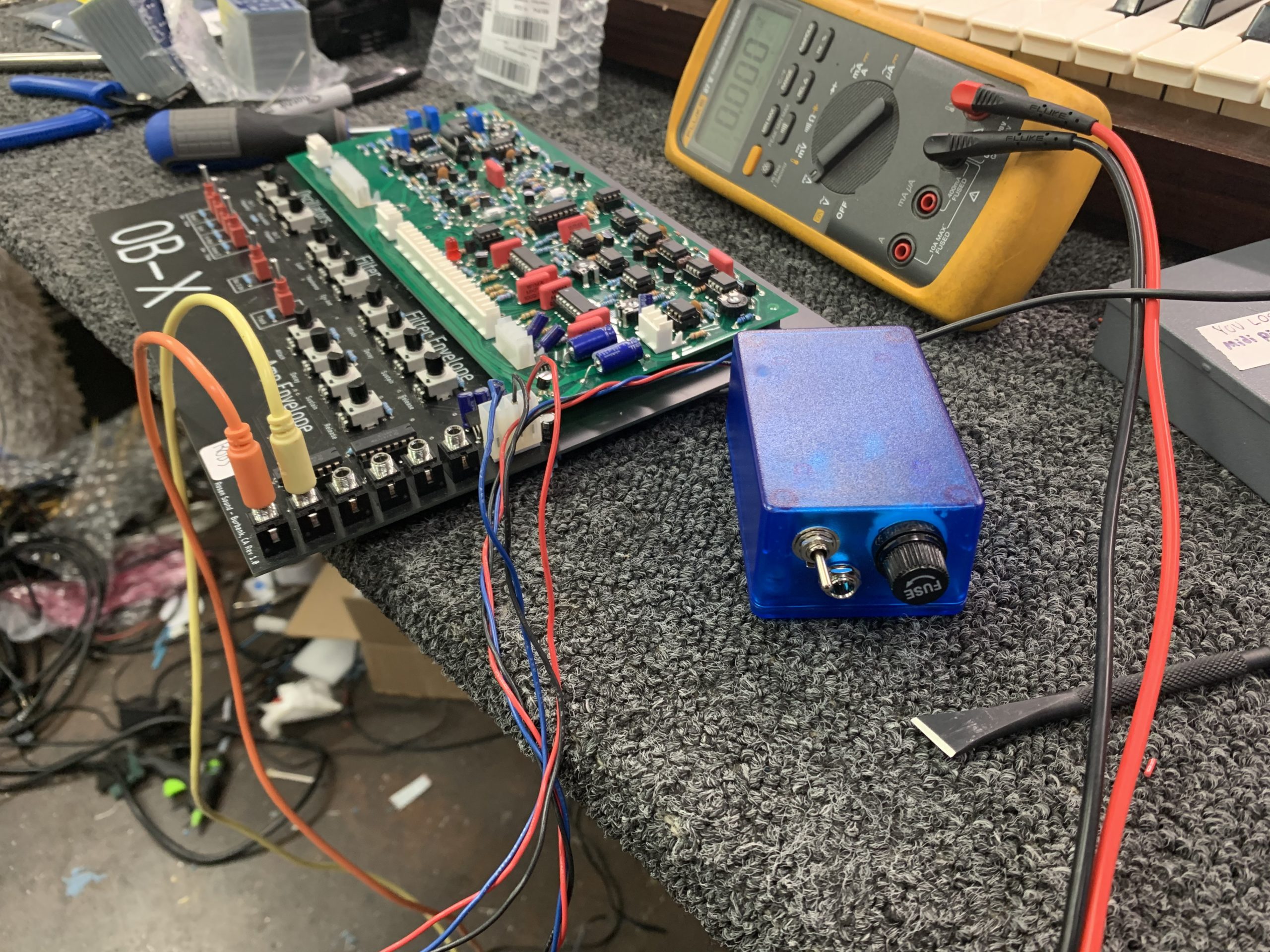

Notice the SMD regulators… that was the main design change. Using through hole LM317/LM337 would have either required a larger board, or a larger project enclosure… Either way resulting in a large project box. The current draw is low enough that these regulators are sufficient. They’re big enough packages to hand solder, too.
One side of the board has easy pads to connect a power switch, the AC jack, and a fuse.The other side has the output voltages with extra pads to make calibration a bit easier.
We will let everyone know via email how much it will cost to have the PSU shipped to them. Again, it will be at cost which is quite low. The most expensive parts are the enclosure ($5) and the wall wart which isn’t much more.
All that’s left is:
1. Resistor values for controller card
2. Stickers
3. Gate levels (if needed, likely not).
Stay tuned…
10/05/2020 Update: Trump has Covid and all parts of this build are ready for delivery!
Happy to report that at this point the project no longer has any mystery pieces. Rev 2 controllers are in and PSU’s are ready to ship to all builders.
The Rev 2 controller simply rationalizes some cuts and jumpers and the only additional feature is the master volume pot. Adding a master volume to the card itself isn’t hard. We will add the needed pot in your PSU box. To add it, lift the negative leg of the capacitor connected to G2, which is the middle pin on header G. Attach the negative lead to the center of the trim pot. Fudge the clockwise pin to the original hole for the capacitor. Use wire if needed. Attach to the counter clockwise leg to a ground point, which can easily be accessed from G1 and G3. Secure with hot glue or silicone and voila, volume has been added.
Some notes:
– Please don’t delete or sub anything from the mouser cart. We had to re-add a few things. If there is something obsolete, please email me so I can update the cart.
– If you haven’t built your controller card yet, check the cart to make sure you got the linear pots and not audio. If you already put in the audio pots, it’s not the end of the world, but use the linear if possible. For Rev 2 builders, use the audio pot for the master volume
– You may opt to not use hardware to mount the card. Up to you. We seem to get a better fit with no hardware.
– If you’d like a rev 2 board, we will only charge for the board at cost and postage. Let me know.
12/11/2020 Update: Pictorials and video all set!
Okay, so now at this point there should be no reason to contact me about cliff hangers for this project!
In the master section above, you will find all pertinent info for building this board including all pictorials, parts placements, whats included, and tips/tricks.
Feel free to reach out as needed! rob@rosensound.com